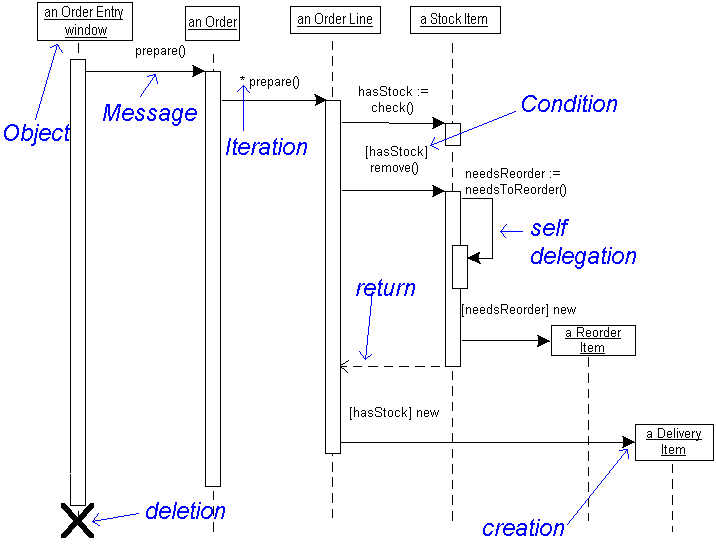

To indicate that it takes a certain while before the receiver actually receives a message, a slanted arrow is used. The messages are drawn as a horizontal arrow. Messages are often considered to be instantaneous, thus, the time it takes to arrive at the receiver is negligible. Only when a target's destruction is set to 'after destructor' do you have to use a destructor. There are other ways to indicate that a target is destroyed during an interaction. Targets that are created during the interaction by a constructor call are automatically placed further down the diagram.Ī destructor message destroys its receiver. The sender that already exist at the start of the interaction are placed at the top of the diagram. Participants can be created and destroyed according to the messages that are being passed.Ī constructor message creates its receiver. Participants do not necessarily live for the entire duration of a sequence diagram's interaction. A signal is an asynchronous message that has no reply.

It is a regular message call used for normal communication between sender and receiver. A synchronous message (typically an operation call) is shown as a solid line with a filled arrowhead.The line type and arrowhead type indicates the type of message being used: As a result, sequence numbers is optional. Ordering is indicated by vertical position, with the first message shown at the top of the diagram, and the last message shown at the bottom. They are drawn from the sender to the receiver. Messages depict the invocation of operations are shown horizontally. Objects work together by communicating or interacting with one another. Objects take on the responsibility for things like managing data, moving data around in the system, responding to inquiries, and protecting the system. Messages between objects are represented by arrows that point from sender object to the receiver object.Įverything in an object-oriented system is accomplished by objects.

Each object also has its timeline represented by a dashed line below the object. Often, an anonymous object (:Account) may be used to represent any object in the class. Object names can be specific (e.g., myAccount) or they can be general (e.g., myAccount :Account). These indicate the existence of the object. A lifeline is represented by dashed vertical line drawn below each object. LifelineĮntities of participants in a collaboration (scenario) are written horizontally across the top of the diagram. The three ways of naming an object are shown in Figure below. An object can be named in one of three ways: the object name, the object name and its class, or just the class name (anonymous object). In the UML, an object in a sequence diagram is drawn as a rectangle containing the name of the object, underlined.


 0 kommentar(er)
